bateske.com
High-Impact Creative Design and Development
High-Impact Creative Design and Development
 |

The Interactive Digital Business Card
|
OLED Screen Piezo Speaker Capacitive Input Buttons 9+ Hours Playtime 1.6 millimeters total thickness |
Circuit boards for the new prototype should be here Monday! I've made some updates to the website, more on the way! - March 29, 2014
Kickstarter Soon! |
|
 Form BusinessDesign New PrototypeIdentify Possible Manufacturers
 First Batch of Manufactured PrototypeBusiness Plan CompleteKickstarter Video Ready
Media Coverage


|
 |
 |
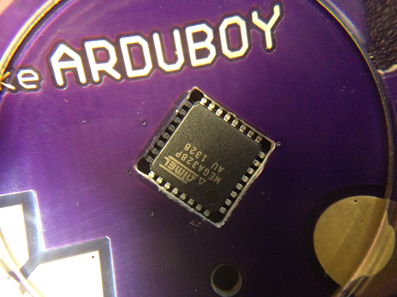 |
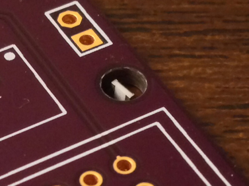
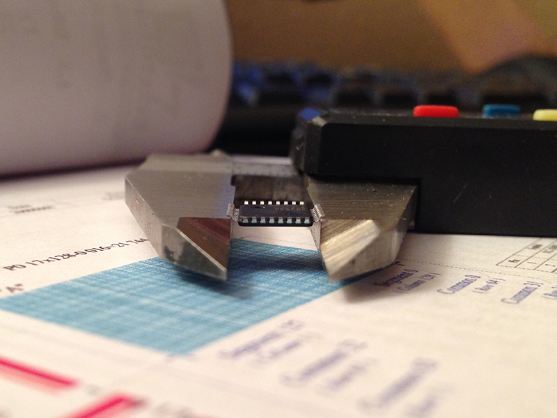
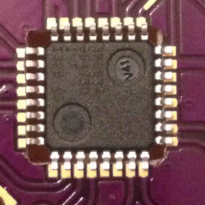
| This happy little accident of dropping an SMD resistor into a drill hole sparked everything. | Careful measurements were made of all components. This is the Atmega 328P inverted, suspended only by it's pins. | The TQFP32 cutout was done by hand by a friend when the board fab omitted the cutout. |
The primary trick of this design is having milled cutouts made for surface mount components to be press fit into, using the circuit board as a kind of frame. Components selected have a thickness near that of the circuit board (1.6mm). Furthermore, to minimize the board thickness, the Atmega328P is inverted so that the bulk of its height below the surface. The result of equal thickness and recessed installation provides a flush appearance. The primary benefit beyond the aesthetic quality is the device is easily slid from a wallet. The high quality boards and the excellent service from oshpark also makes this build possible.
 |
 |
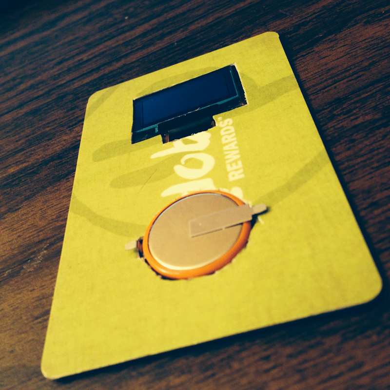 |
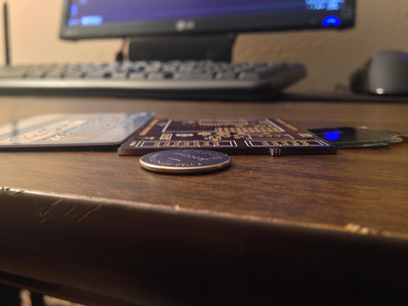
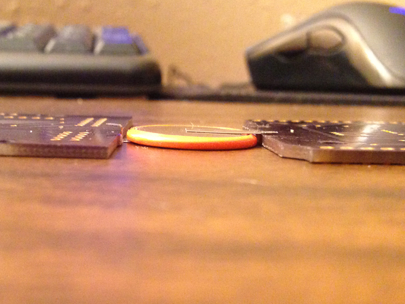
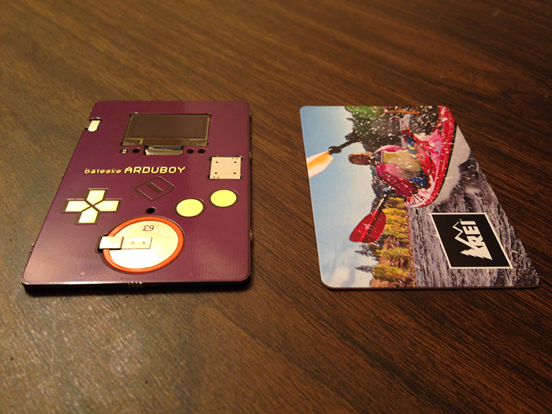
| Left to Right: Credit Card, Circuit Board, Standard CR2016 Battery, OLED Display. | Another key stage in the process was finding a CR2016 with low profile solder tabs. | A Qdoba card goes under the knife to test out the cutout concept. |
Inspiration struck when I was working with the OLED module. For some time I had been pondering the best method for protecting and otherwise accounting for the flex ribbon on the screen within the design of the circuit board. When prototyping, the screen laid flat against the breakout board and this felt like the most natural orientation for the display to be installed. Placing a circuit board next to the OLED screen revealed near identical height and in that moment I knew it was time to get to work.
Within Cad soft Eagle I had to create footprints with the cutouts for each component I wanted to use. This meant carefully consulting the specification sheet of each part. In addition to careful attention to the parts themselves, the tolerances and tool dimensions of the circuit board fabrication house had to be considered. The fine-tuning of this part of the project is still ongoing.
This project originated from piecing together boards from adafruit and sparkfun. I became interested in developing the ability to control the devices directly, by replicating the circuits of the boards I bought. The beauty of open source technology is that the schematics were available from both vendors so I could easily begin learning.
 |
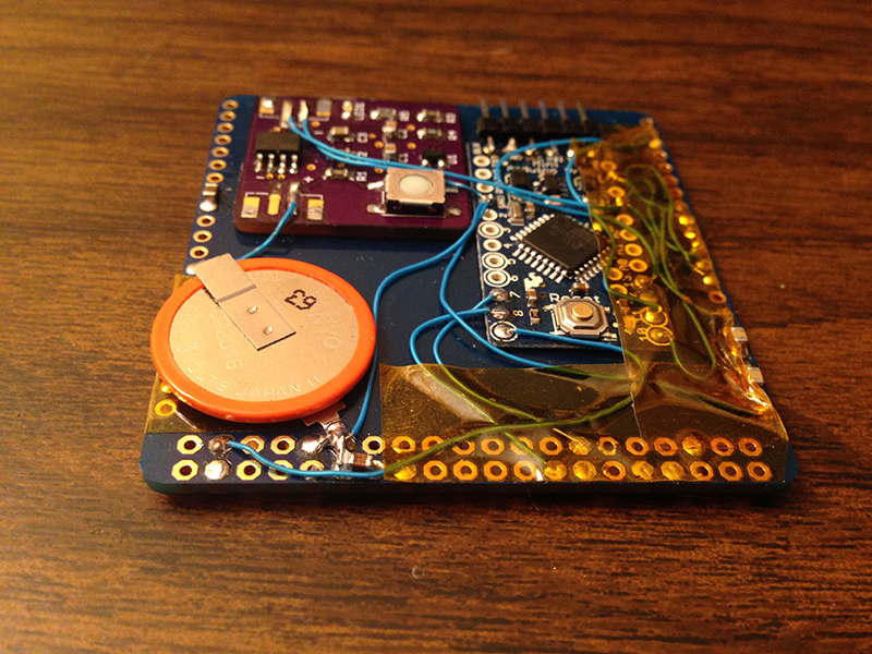 |
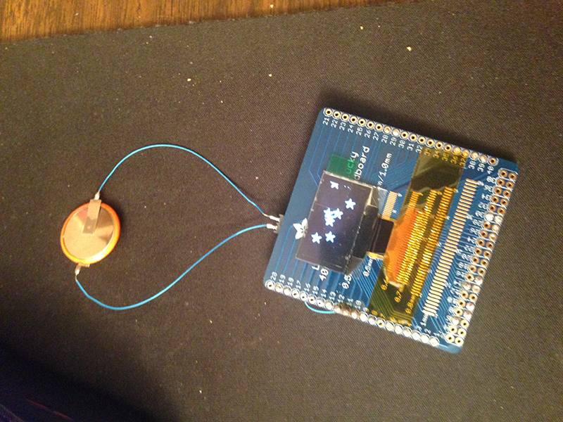
| Here is the first hardware test. I love adafruit products, this breakout board is awesome! | Arduino Pro-Mini is attached by double sided tape along with a push-on/hold-off circuit to the back. |
In this design, each component that is in the circuit will require its own cutout. The challenges of designing a single sided circuit also meant a smaller number of supporting components is desirable. I was on a quest to remove all but the most necessary of filter capacitors and current limiting resistors. With a very limited set of electrical engineering skills, I set to work. Replicating the schematics according to the reference diagram, I removed parts one by one until the circuit no longer functioned.
In the end I was able to develop a circuit that only required 5 filter capacitors, beyond the primary devices. Testing shows I don't even need the filter capacitor on the main processor, but I leave it there for safety sake. Omitting the AC filter capacitors on the OLED will cause it to have banding, but will otherwise work just fine. So if the situation allowed, this could be reduced to only the two capacitors on the OLED's internal power supply. Current limiting resistors have been omitted since the battery is unable to output enough current to damage anything.
A prototype is tested to last well over 10 hours continuous playtime. Sound impressive considering what it is, the volume is good as long as you use a single channel. I have tied two output pins together driving the speaker which allows either polyphonic sound or output doubling. When configured for polyphonic sound, the volume goes down as a result of the sinking/sourcing going on between the pins. Output doubling is as of yet untested but should increase the volume to annoying levels. I used adafruits values for the AC filter capacitors on the OLED screen which gave the best results at 3 volts.
Capacitive touch pads have been made into the top copper of the board. At design I unwittingly tied the A and B pads to the XTAL pins, available since I'm using the internal oscillator. As I came to find out, accessing them isn't too difficult just requiring direct port access within the arduino framework. This turned out to be an excellent learning experience. Performance is best when you have a firm grip on the card to establish a ground loop. Not many people hold the card this way since it appears fragile so it requires some encouraging to get comfortable with the card. I would love to make this interrupt driven but as of now, my neck beard is not strong enough.
 |
 |
| You can see the board before the cutout was made for the Atmega. Unfortunately no bananas were available at the time to show scale. While unrelated to this post, I also really love REI. | A close-up of the mounting configuration. Some small sanding helped bring this into better alignment than you see here. |
The board required sanding to get the parts to fit and the TQFP cutout was omitted by the fab house in the first prototype. I'm working to get this resolved and this is one of the reasons why I'm not ready to release the board and library files just yet. As far as durability, I'm keeping the only working prototype in my wallet... So far so good!
After completing the first set of tests on the prototype, I have made the following adjustments accordingly. Modifications to the component cutouts were required for manufacturing tolerances. I have decided to change to resistive touch pads for more consistent feedback, which will also enable the use of existing pin change interrupt libraries. Ideally I favor capacitive touch as it provides pressure feedback but the lack of an interrupt driver makes it impractical at present.
This is a blank canvas and now the opportunity to create games of all shapes and sizes. My real dream is this: is to see someone love this enough to develop something truly unique for the platform.
It would be beautiful to see mario coded in assembly, but that might be too much of a pipe dream...
I want to release the design files and source code under a fully open source license. I would like to do a crowd sourced campaign to publish the files. I also would like to sell these as kits on my site and on tindie.
^ The sales pitch
In order to release board files, eagle library and arduino sketches that have already been developed, they require additional work to be fit for general consumption by the community. Mostly this means cleaning up the code and other housekeeping items but it is my intention to add value as well.
I would like to design the board with test points to be placed in standard ISCP and FTDI configuration, eliminating the need for an otherwise custom bed-of-nails programming interface.
^ What I want to crowd source
In order to manufacture the Arduboy there will be further development costs and overhead in having this mass produced. The goal will be set as low as possible to be able to begin producing the Arduboy as soon as possible!
^ What the fund raising goal might be
Furthermore I would very much enjoy to continue producing radical new design concepts. If the campaign exceeds it's goal I promise that any of the additional "profits" will be reinvested in new amazing projects that I can share with everyone once again.